Documentation and integration notes for the RPi CM5 interface board in the Open-Source Leg stack.
The Interface Board is a carrier board for the Raspberry Pi Compute Module 5 (RPi CM5) that provides power input, safety, and standardized connectors so the CM5 can be integrated into robotics systems quickly and consistently. It consolidates common I/O (GPIO, I2C, SPI, UART, CAN, and fan control), exposes reliable power paths, and adds board-level features that simplify bring-up and maintenance. The board is built and tested by researchers at the University of Michigan Neurobionics Lab for use across the Open-Source Leg stack.
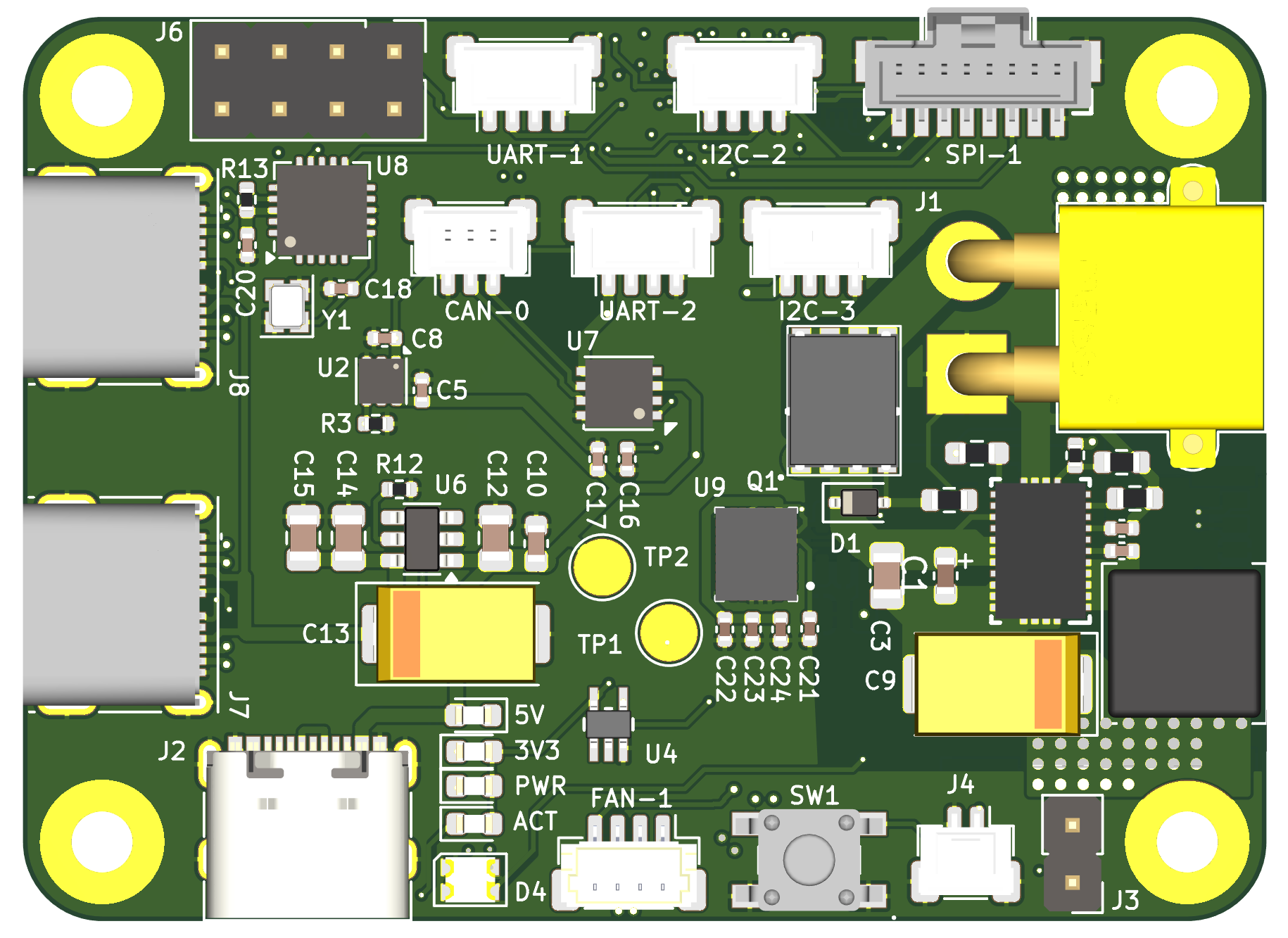
Click the board to explore connectors, features, and pinout callouts.
Input and output power specifications at a glance.
Input and output power specifications.
| Designator | Connector | Voltage (V) | Power (W) |
|---|---|---|---|
| J1 | XT30 | 15 - 42 | 30.2 |
| J2* | USB-C | 5 | 26.5 |
*Do not use J7 or J8 USB-C ports for power input. These are for high-speed data transfer only.
The peripheral connectors can provide a combined power output of 1 W at 3.3 V.
Connector map, bus details, and mating parts.
| Designator | Bus details | Connector | Mating part no. |
|---|---|---|---|
| I2C-2,3 | I2C-2, I2C-3 | Molex PicoClasp, 4-Pin | 5013300400 |
| SPI-1 | SPI-1 (CS0, CS1, CS2) | Molex PicoClasp, 8-Pin | 5013300800 |
| UART-1,2 | UART-1, UART-2 | Molex PicoClasp, 4-Pin | 5013300400 |
| CAN-1 | CAN-0 (on SPI-0, CS0) | Molex PicoClasp, 3-Pin | 5013300300 |
| FAN-1 | Fan PWM, Fan Tacho | JST PH 4-Pin | SHR-04V-S-B |
| J6 | GPIO 7, 22, 23, 24, 25, 27 | Header Pins, 8-Pin, 2.54 mm pitch | - |
Note: Pins can be remapped using RPi Device Tree Overlays in /boot/firmware/config.txt. For more details, refer to this link.
Explore onboard features and component details.
Step-by-step bring-up instructions for first power-on.
Step 1
Jump the J3 header pins to put the CM5 into storage mode.
Step 2
Set up your host device (personal computer) and install rpiboot to detect the CM5 as a storage device by following these instructions.
Step 3
Install the CM5 on the interface board and connect to the host device using USB J2.
Step 4
Run rpiboot following these instructions and after a few seconds, the CM5 should be detected as a mass-storage device.
Step 5
Flash an operating system image using an imaging tool like Raspberry Pi Imager. We highly recommend using the Robot-CI image by the Neurobionics Lab that auto-configures the peripheral ports to function with the interface board. Please follow the instructions in the repository descriptions to generate this image, and make sure to check the Are you using the Neurobionics Interface Board checkbox.
Step 6
Check to make sure your user account has sudo access and access to the required sensor groups (spi, i2c, gpio). If not, add the following groups:
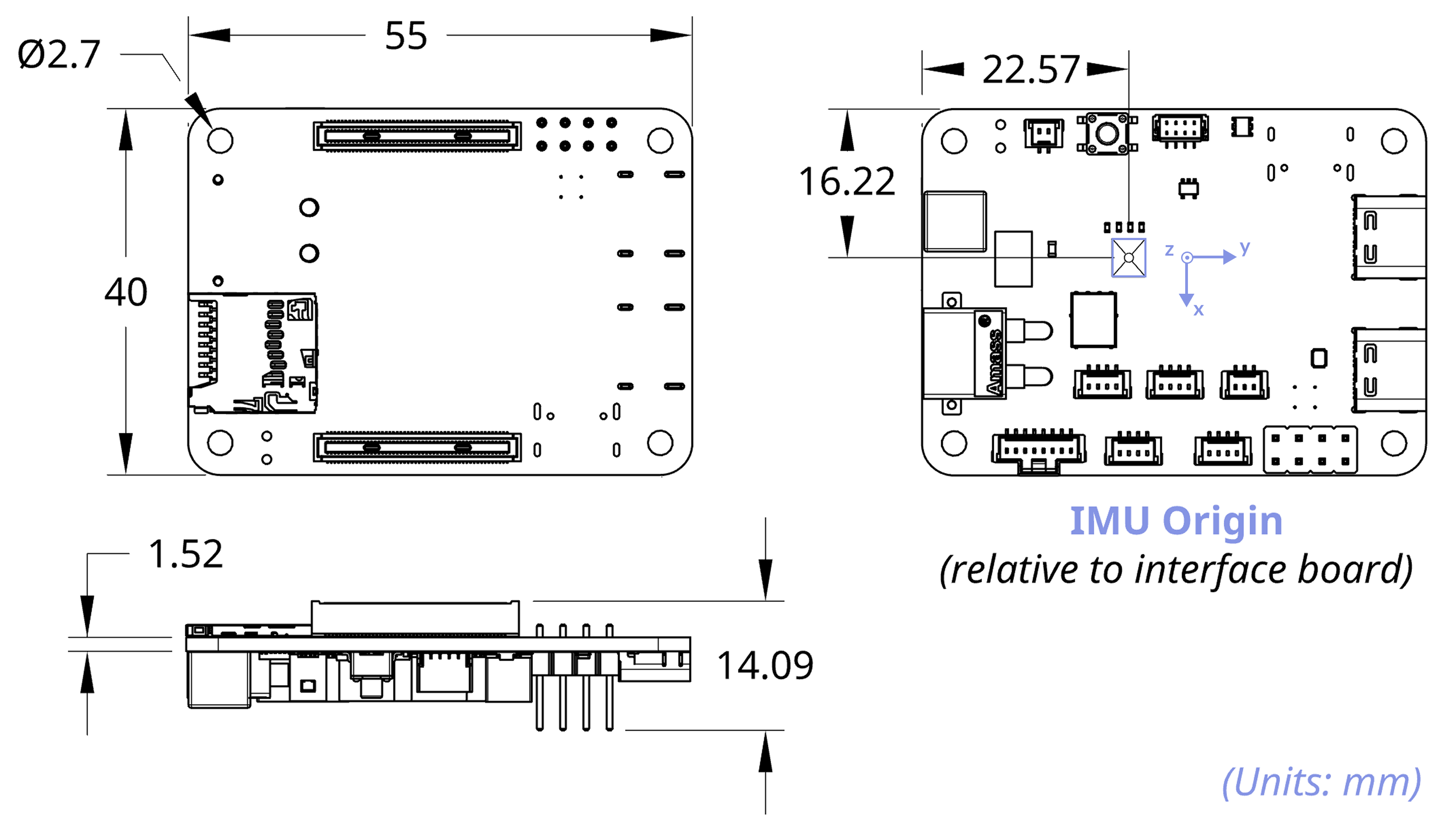
sudo usermod -aG <GROUP> <USERNAME>Mechanical dimensions and mounting details.
Mechanical dimensions and mounting specifications for the interface board.
Cooling, grounding, and strain-relief guidance.
Since the RPi CM5 tends to run hotter than the standard RPi 5, we strongly recommend using active cooling (via the FAN-1 port) or a passive heatsink, along with ensuring adequate ventilation.
For improved noise immunity in high-interference environments, use shielded cables for sensors and ground the interface board to the hardware chassis.
Provide adequate strain relief on all wiring to reduce mechanical stress and maintain signal integrity.
Version history and changelog for the RPi CM5 Interface Board:
| Version | Release Date | Changes | Datasheet |
|---|---|---|---|
| v1.1.0 | December 2025 | New Features
Changes
| Coming Soon |
| v1.0.0 | October 2025 | New Features
Fixes
| Download |